9. LDR-sensor
LDR sensor connection diagram
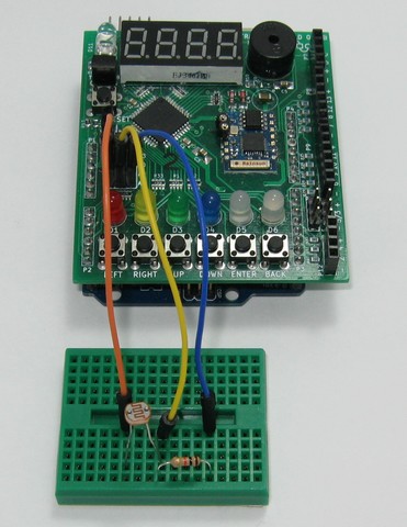
Exercises
Compile and upload the following program to the Arduino. Observe how the measured values change as the LDR sensor is more or less illuminated.
 1
 2
 3
 4
 5
 6
 7
 8
 9
10
11
12
13
14
15
16
17
18
19
20
21
22
23
24
//
// Sensor LDR
//
#include <Picuino.h>

// Inicia Arduino
void setup() {
   pio.begin();
   Serial.begin(19200);  // Inicializa el puerto serie
}

// Bucle principal
void loop() {
   // Lee la señal producida por el sensor LDR
   int ldr = analogRead(A1);

   // Muestra la señal por pantalla
   pio.dispWrite(ldr);
   Serial.print("LDR = ");
   Serial.println(ldr);

   // Espera medio segundo
   delay(500);
}
Make a program that emits different notes depending on the light received by the LDR sensor. Replace the wait time in the previous program with the following lines of code.
1
2
3
4
5
// Theremin con sensor LDR
pio.buzzTone(500 + ldr*2);
delay(64);
pio.buzzTone(0);
delay(128);