2. The relays
Relays are the first electrical devices used in electrical automation.
In this unit we will study the history of the relay, its operation, the most common electrical diagrams and various types of relays.
The relay. Editable format DOC
What is a relay
It is an electromechanical device with two components: the coil and the contacts. The coil receives a small electrical current at low voltage in the control circuit and moves the contacts that act as switches for higher current and voltage in the power circuit.
In this way we achieve that a small electric current is capable of moving high power circuits.
Relay operation
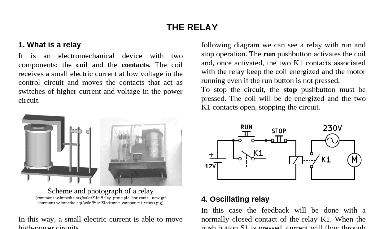
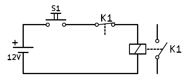
In the following diagram we can see the circuit of a relay in operation.
The control circuit is on the left and consists of a 12 volt battery, a push button and the relay coil. When the button is pressed, the current reaches the coil and the power contact (switch) is activated.
The power circuit consists of a relay contact, a 230 volt alternating current generator and a motor. When the contact closes, voltage reaches the motor and it starts up.
Circuit of a relay fed at 12 volts that drives a 230 volt motor.
An advantage of this design is that the push button has a safe voltage for people, separated from the high voltage of the motor, which is more appropriate to supply large powers.
Feedback relay
A relay has several contacts, some normally open and some normally closed. These contacts can be used to feed back the drive circuit so that it remains operational once the relay has been activated.
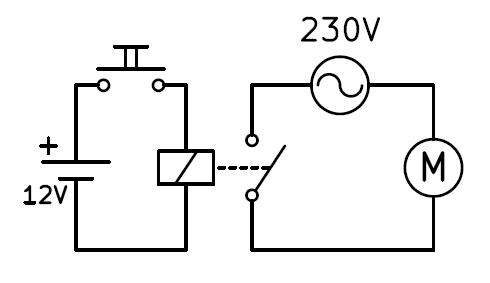
In the following diagram we can see a relay with start and stop operation. The start button activates the coil and once activated, the two K1 contacts associated with the relay keep the coil energized and the motor running even if the start button is released.
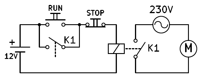
Diagram of a relay with start and stop buttons that activates a 230 volt motor.
For the circuit to stop, the stop button must be pressed. The coil will stop having current and the two K1 contacts open stopping the circuit.
Oscillator relay
In this case, the feedback will be done with a normally closed contact of relay K1. When pushbutton S1 is pressed, current will flow through the coil. The coil will act by moving the contacts and the normally closed contact K1 will open. When this contact opens, current will stop flowing through the coil. The coil will stop acting, with which the contact K1 will close again allowing current to flow through the coil.
Oscillating relay with a normally closed contact.
The result will be an oscillation in which the relay will vibrate over and over again, opening and closing its contacts as fast as its design allows.
Relay history
The relay was invented in 1835 and began to be used in telegraphy to amplify long-distance signals. As the relay is capable of controlling an output power greater than the input power, it can be considered an amplifier that allowed to increase the quality of the telegraph signals.
In 1941 Konrad Zuse built the first relay-based computer. The relays were later replaced by much faster vacuum tubes. Starting in 1954, transistors began to be used, even faster and much more reliable. Currently, transistors are still used in computers and in a multitude of electronic devices.
Although relays are no longer used as the basis of computers, they are still frequently used today in automation to control motors and other high-power elements. Examples can be found in houses to move elevators, water pumps or the stair light timer.
Contactors
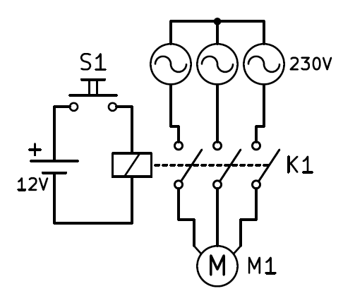
Contactors are special high-power relays that are used to move three-phase motors, that is, they have three power supply lines.
In the following drawing you can see the schematic of a contactor feeding a three-phase motor. In this circuit you can appreciate the value of relays to handle large powers and switch many circuits with a small low voltage signal.
Exercises
- What is a relay and what is it for?
- Draw the schematic of a relay that turns on a 125 Volt light bulb from a 24V powered push button.
- Draw the schematic of a relay that turns on a 23 Ohm resistor powered at 220V with two buttons, one for start and the other for stop. Explain how the circuit works.
- Draw the two states of an oscillating relay while the push button is pressed.
- What uses has the relay had throughout history? What is it currently used for?
- What electronic components replaced the relay?
- What is a contactor and why is it used?
- Draw the schematic of a contactor that will always run a motor until a normally closed contact is pressed.