10. The truth table
In previous topics we have seen what a truth table of a logic gate is. In this topic we are going to see, step by step, how to create the truth table of any combinational circuit.
The steps to create the truth table of a circuit are:
Name each of the circuit inputs with a capital letter of the alphabet, A, B, C, etc.
Name each of the outputs of the circuit with an O plus a number, O1, O2, O3, etc.
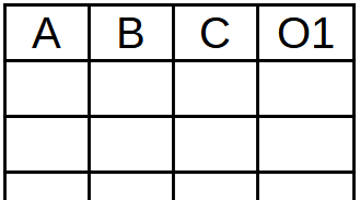
Draw a table with as many columns as the number of inputs plus the number of outputs the circuit has.
In the first row of the table we will place the name of the entries A, B, C, etc. and the name of the outputs O1, O2, O3, etc.
Finish drawing as many rows as necessary in the table (2 to the number of entries).
For 2 entrances, 4 rows.
For 3 entries, 8 rows.
For 4 entries, 16 rows.
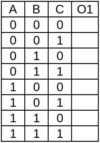
Number the rows corresponding to the entries in binary.
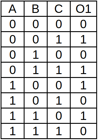
For each combination of inputs, calculate the outputs of the circuit and draw them in the table.
Solved exercise
Draw the truth table of the following circuit with 3 inputs and 1 output.
We name the entries as A, B, C.
We name the output as O1.
We draw the table and in the first row we place the name of the inputs and outputs.
We finish drawing the table with 8 free rows (2^3 = 8) to be able to number all the possible entries.
We number the rows corresponding to the entries in binary.
Finally we place each of the 8 combinations of inputs in the circuit and write their output in column O1.
Exercises
Draw the truth table of the following circuit.
Draw the truth table of the following circuit.
Draw the truth table of the following circuit.


