9. The simultaneity valve or AND valve
The simultaneity valve or AND valve allows the passage of pressurized air when both inlet ports, right and left, receive pressurized air.
The summarized operation can be explained by saying that the valve allows pressurized air to pass when pressurized air reaches it through the left channel and pressurized air also reaches it through the right channel, hence its name.
The symbol at rest of the simultaneity valve is as follows:
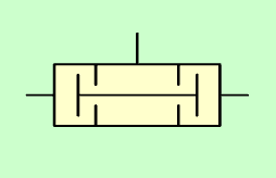
Simultaneity valve or AND valve.
When pressurized air is injected through the right channel, the central piece will move to the left, preventing the passage of air.
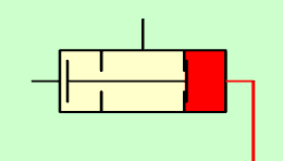
Simultaneity valve with pressure in the right track.
When pressurized air is injected through the left channel, the central piece will move to the right, also preventing the passage of air.
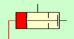
Simultaneity valve with pressure in the left track.
When pressurized air is injected through the right and left channels, the central piece cannot close both channels at the same time, so it allows the passage of pressurized air, which will come out through the upper channel.
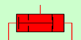
Simultaneity valve with pressure in the right and left tracks.
The operation of the simultaneity valve can be summarized in the following truth table or logic table:
| Left track | Right track | Upper route |
|---|---|---|
| No pressure (0) | No pressure (0) | No pressure (0) |
| With pressure (1) | No pressure (0) | No pressure (0) |
| No pressure (0) | With pressure (1) | No pressure (0) |
| With pressure (1) | With pressure (1) | With pressure (1) |
Single-acting cylinder and simultaneous valve
In this circuit, a single-acting cylinder is actuated by two 3/2 valves only when both are actuated.
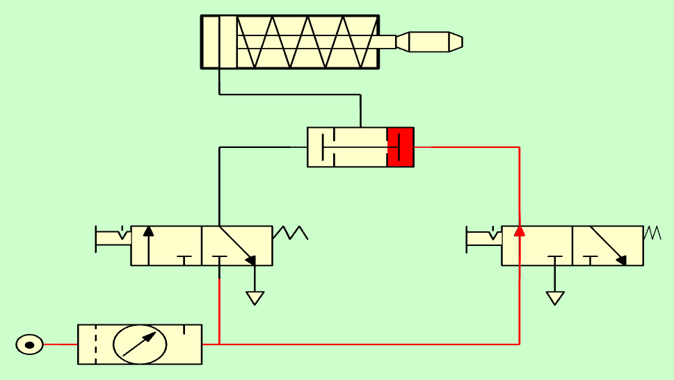
In the following figure you can see the circuit at rest:
Single-acting cylinder with pressureless simultaneous valve.
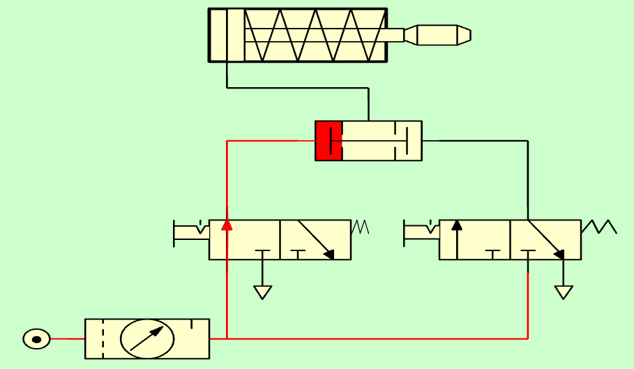
When we activate the left valve, the pressurized air reaches the simultaneous valve, but it does not allow the pressure to pass through the upper passage.
Single-acting cylinder with simultaneous valve with pressure on the left.
When we also activate the right valve, the pressurized air reaches the simultaneous valve from both sides and cannot stop both air flows, so it allows pressurized air to pass through the upper passage. The rod of the single-acting cylinder will come out.
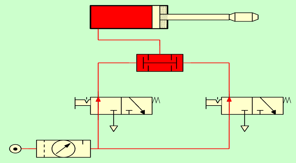
Single-acting cylinder with simultaneous valve with pressure in both inlets.
Simulates the operation of the simultaneity valve in the following circuit:
Valve union
In a pneumatic circuit we can combine several selector and simultaneity valves to achieve complex behaviors.
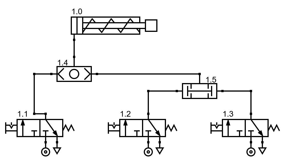
In the following circuit we can see two different valves (one simultaneous and another selector) that combine the pressurized air from three 3/2 valves to a single-acting cylinder.

Simultaneity and selector valves in cascade.
In the previous circuit, the cylinder rod will come out when the left valve 1.1 is pressed and, at the same time, one of the two valves on the right (valve 1.2 or 1.3).
In the following circuit we can see another different combination of simultaneous and selector valves towards a single-acting cylinder.
Simultaneity and selector valves in cascade II.
In the previous circuit, the cylinder rod will come out whenever we activate the left valve 1.1 or when we activate both valves on the right (valve 1.2 and 1.3).
Exercises
Draw the symbol at rest of a pneumatic simultaneity valve.
Draw the operation of a pneumatic simultaneous valve when it receives pressurized air from the right side.
Draw the operation of a pneumatic simultaneous valve when it receives pressurized air from the left side.
Explain the operation of the pneumatic simultaneity valve and draw its truth table.
It simulates the operation of a single-acting cylinder with a rod that must come out when the two 3/2 maneuver valves** are activated at the same time.
Draw the above circuit on paper and explain its operation.
What is the purpose of combining simultaneous valves and selector valves in cascade?
Simulates a circuit that has three 3/2 valves that operate a single-acting cylinder.
The cylinder rod must come out when either of the two valves on the left are activated and at the same time the valve on the right is activated.
Draw the above circuit on paper and explain its operation.
Draw the truth table with the operation of the previous circuit by completing the following table.
Left valve 1 Left valve 2 Right valve Rod Not actuated Not actuated Not actuated Inside Powered Not actuated Not actuated Not actuated Powered Not actuated Powered Powered Not actuated Not actuated Not actuated Powered Powered Not actuated Powered Not actuated Powered Powered Powered Powered Powered