8. The selector valve or OR valve
The selector valve or OR valve allows pressurized air to circulate from any of the ports on both sides to the upper port. This valve does not allow the passage of pressurized air from the right track to the left track or vice versa.
The summarized operation can be explained by saying that the valve allows pressurized air to pass when pressurized air arrives through the left channel or through the right channel, hence its name.
The symbol at rest of the selector valve or OR valve is as follows:
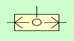
Selector valve or OR valve.
When pressurized air is injected through the right passage, the central ball will move to the left, allowing air to pass through the upper passage and preventing air from escaping through the left passage.
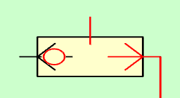
Selector valve with pressure in the right track.
The operation is similar when pressurized air is injected into the left channel, allowing the pressure to pass through the upper channel and not allowing pressurized air to pass through the right channel.
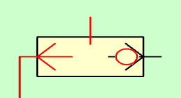
Selector valve with pressure in the left track.
When pressurized air is injected through the right and left passages, the pressurized air exits through the upper passage.
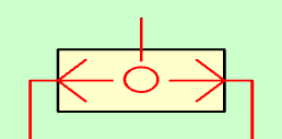
Selector valve with pressure in both inlet ports.
Note
The selector valve is different from a simple pipe union because it prevents pressurized air from escaping through the non-pressurized path.
The operation of the selector valve or OR valve can be summarized in the following truth table or logic table:
| Left track | Right track | Upper route |
|---|---|---|
| No pressure (0) | No pressure (0) | No pressure (0) |
| With pressure (1) | No pressure (0) | With pressure (1) |
| No pressure (0) | With pressure (1) | With pressure (1) |
| With pressure (1) | With pressure (1) | With pressure (1) |
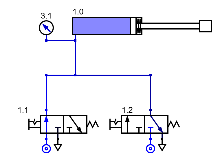
Single acting cylinder and selector valve
In the following simulated circuit, a single-acting cylinder is actuated by two 3/2 valves interchangeably. That is, when you activate either of the two valves, the cylinder rod will come out:
In the following figures you can see the cylinder activated from the left valve and from the right valve.
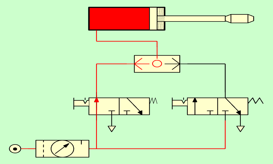
Single-acting cylinder with selector valve with pressure from the left.
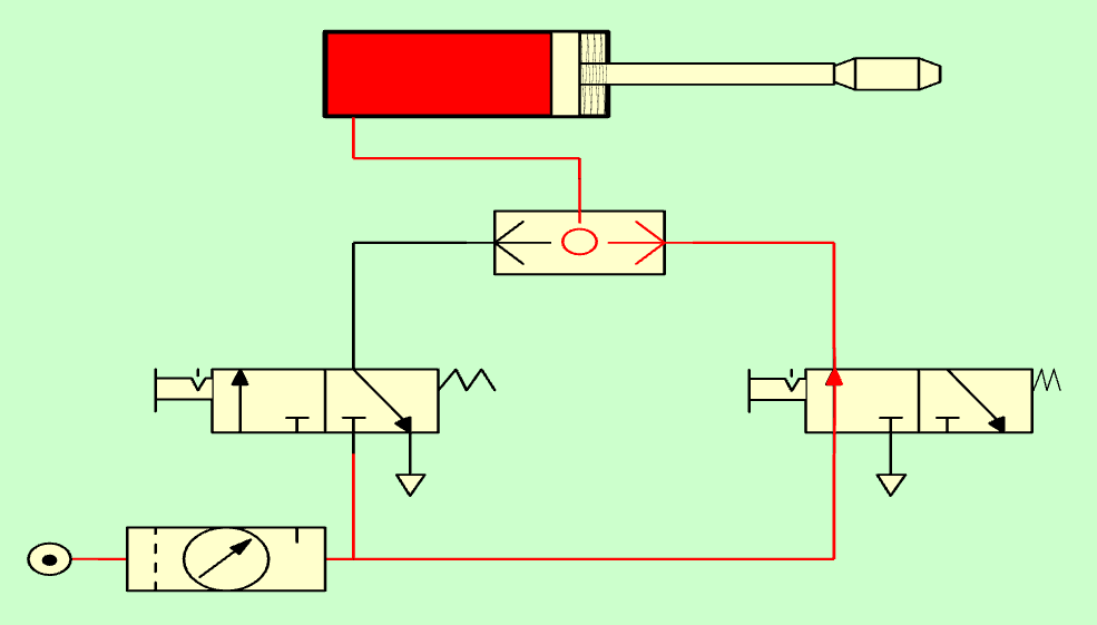
Single-acting cylinder with selector valve with pressure on the right.
It is interesting to see how the pressurized air is not lost through the exhaust of the valves at rest, because the selector valve prevents the pressurized air from leaving through the non-pressurized path.
If both valves are activated, the cylinder rod will also come out.
Operation of a pipe joint
The operation of a pneumatic tube union is somewhat similar to that of a selector valve, with the difference that the pressure from one path can escape through the other path if it is without pressure:
Single-acting cylinder with tubes connected doing the OR function.
In the previous circuit, the pressurized air coming from the left valve reaches the cylinder and forces its rod out, but pressure is also lost through the right valve that is connected to the exhaust. This can be seen on the pressure gauge, which does not reach the 6 bar compressor pressure.
The final result is that the pressurized air will come out all the time through the exhaust of the valve at rest, making a lot of noise, wasting air and reducing the pressure of the tube and the force with which the single-acting cylinder comes out.
Union of selector valves
The pneumatic selector valves can be arranged in cascade to join more than two pneumatic control valves in a single air outlet path.
The operation of cascade valves is similar to that of a single valve. If any of the side passages receive pressurized air, this pressurized air is directed to the upper passage.
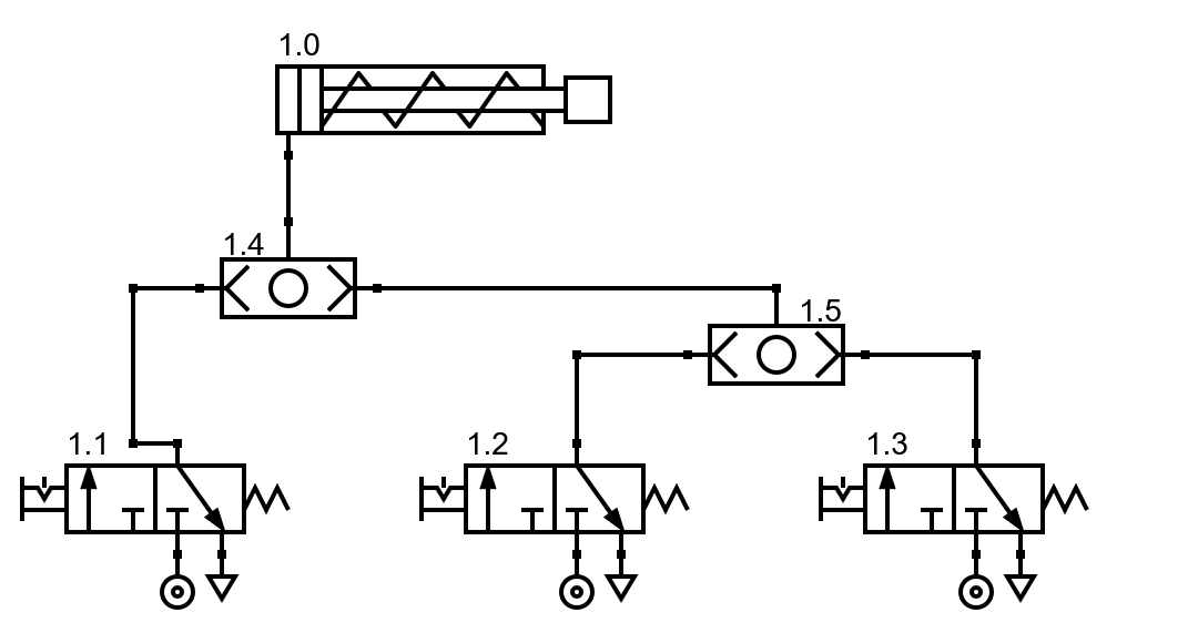
Union of selector valves in cascade.
Exercises
Draw the symbol at rest for a pneumatic selector valve.
Draw the operation of a pneumatic selector valve when it receives pressurized air from the right side.
Draw the operation of a pneumatic selector valve when it receives pressurized air from the left side.
Explain the operation of the selector valve and draw its truth table.
Simulates the operation of a single-acting cylinder with a rod that must come out when activating any of the two 3/2 maneuver valves:
Draw the above circuit on paper and explain its operation.
Simulate the operation of a pneumatic tube joint in the simulator:
Draw the above circuit on paper and explain its operation.
What are the differences between a pneumatic selector valve and a pneumatic tube union?
What is the purpose of combining pneumatic selector valves in cascade?
Simulates a circuit that has three 3/2 valves that operate a single-acting cylinder. The cylinder rod must come out when any of the three individual valves are actuated.