14. Nested Sketch Extrusion
In this practice we are going to create sketches to extrude them, placing some sketches on top of others and thus form more complex figures.
Open the FreeCAD application and click on the icon to create a new document
 .
.We select the Part Design workbench
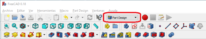
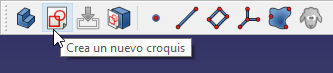
Next we select to create a new sketch.
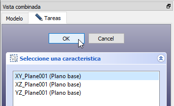
And we choose the XY plane as the base plane to place the new sketch.
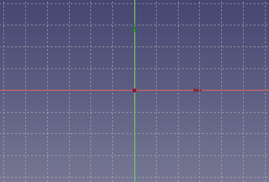
A grid will appear on the screen where you can draw in two dimensions.
Next we are going to draw a simple object, an octagon.
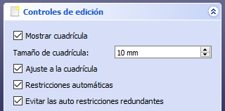
First we adjust the editing controls in the Tasks tab, so that the drawing will fit on the grid.
Now we will create an octagon with the icon polyline
 .
.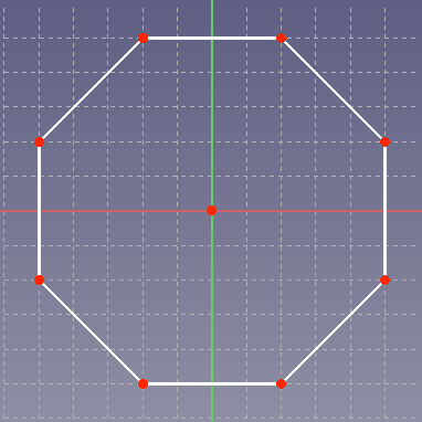
If we make a mistake when placing the points, once the drawing is finished we can click on the points and drag them with the mouse to their correct position.
Once we are done, click on the Tasks tab and click on the
Closebutton. Our drawing will look in plan view as in the following figure.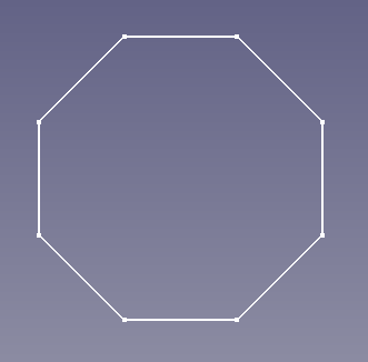
If you can't see the drawing, Click on the 'Fit full content to screen' icon
 .
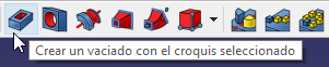
.To get a piece in three dimensions we are going to extrude our sketch by selecting the corresponding icon.
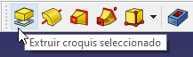
Or selecting in the Menu
Part Design... ExtrudeIn the extrusion parameters we choose the dimension or height that we want for the piece, in this case 50 millimeters.
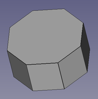
If we switch to perspective view, we will be able to see our octagon in three dimensions.
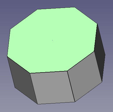
Now we are going to select the upper area of the octagon by clicking on it. The area will turn green.
Once the upper face is selected, we click again on the icon to create sketches.
This time the sketch will be drawn on the selected face, not on the ground.
We re-adjust the editing controls to fit the grid.
And we draw another smaller octagon on top of the first octagon.
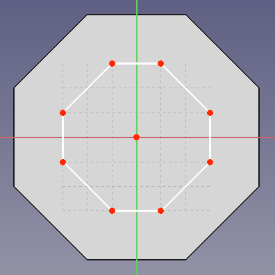
Once we are done, click on the Tasks tab and click on the
Closebutton. Our drawing will look like the following figure.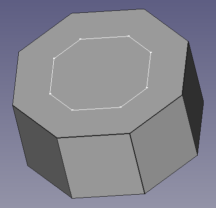
Next we extrude the new sketch to form a new figure on top of the first one. Click on the corresponding icon.
Or we select in the Menu
Part Design... ExtrudeIn the extrusion parameters we choose the dimension or height that we want for the piece, in this case 50 millimeters.
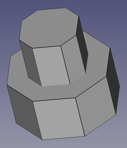
The piece will look like the following image.
Now we are going to generate a shell in the created part. We start by selecting the top face of our object in three dimensions.
Once the top face is selected, we create a new sketch.
We re-adjust the editing controls to fit the grid.
And we draw a square in the center of the piece.
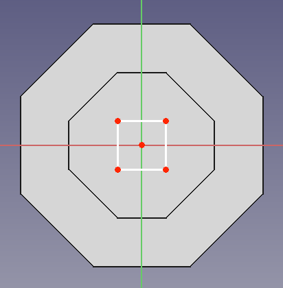
Once we are done, click on the Tasks tab and click on the
Closebutton. Our drawing will look like the following figure.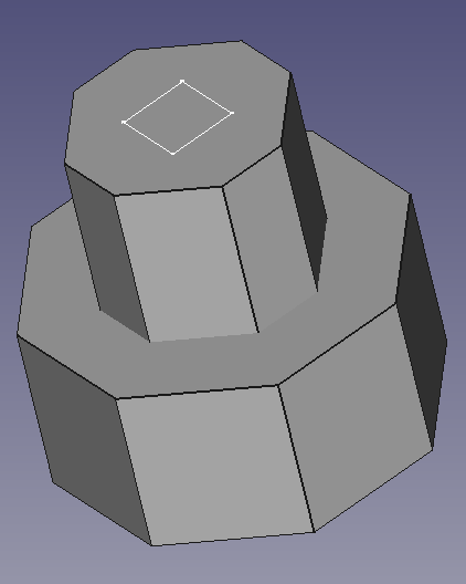
Next we generate a hole from the sketch drawn by clicking on the hollow icon.
Or by selecting in the Menu
Part Design... ShellOnce pressed, we change the shell parameters so that the hole goes through all objects.
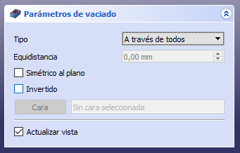
By clicking the
OKbutton, the part will be pierced as can be seen in the following figure.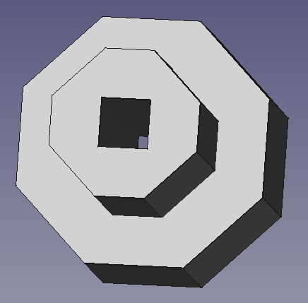
So far we have always created sketches vertically, from the bottom up, but the sketches can be placed on any surface as can be seen in the following figure.
Exercises
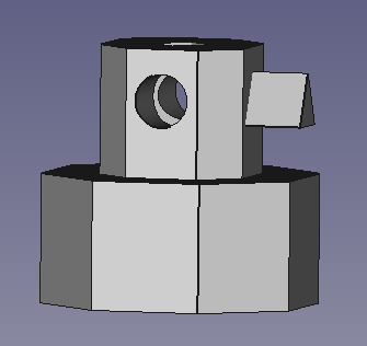
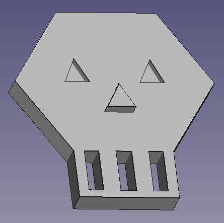
Create a 3-dimensional mask like the one in the figure.
Create a house like the one in the figure.
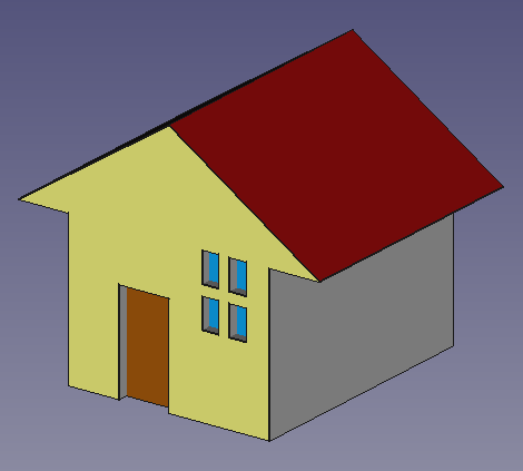
The first sketch with the body of the house will be placed in the XZ plane and extruded in the Y plane.
The following sketches will serve to make holes in the main body.

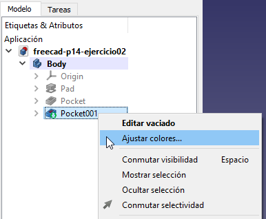
To give colors to the house we will follow this procedure.
- We select the complete house in the Model tab.
- With the right mouse button on the model, we select adjust colors.
- We select with the mouse the face of the object that we want to change color.
- We select the color in the Tasks dialog box.
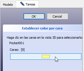
- Click on
OK.
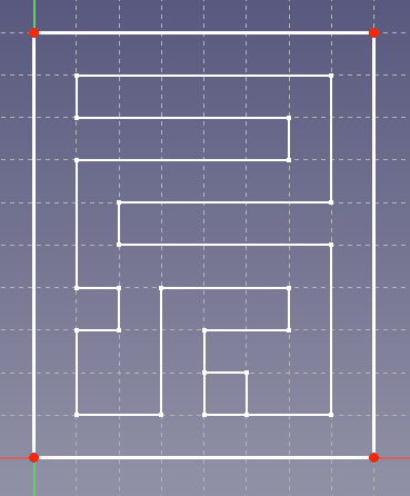
Create a ball maze game like the one in the figure.
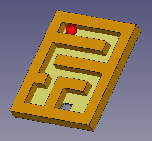
From the following sketches.
Add a sphere with the Part workbench and translate the sphere as you can see in the first figure.
Finally, change the color of the faces of the object and the sphere.