6. Rotation of parts
In this tutorial we are going to learn how to twist and rotate solids.
Open the FreeCAD application and click on the icon to create a new document
 .
.We select the Part workbench to start designing objects in 3 dimensions.
At this point we are going to add the reference axes to help us place the pieces correctly.
In the menu
View... Activate or deactivate the cross of the axes.In English
View... Toggle axis cross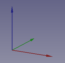
Now we create a cube by clicking the first icon on the solid object bar.
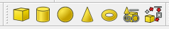
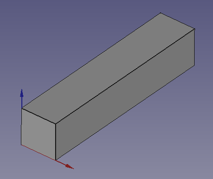
and we resize the cube according to the following dimensions.
Length (Length) = 2
Width = 10
Height (Height) = 2
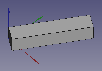
Now we select to see the piece in isometric view.
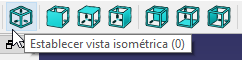
The piece will look like the following image.
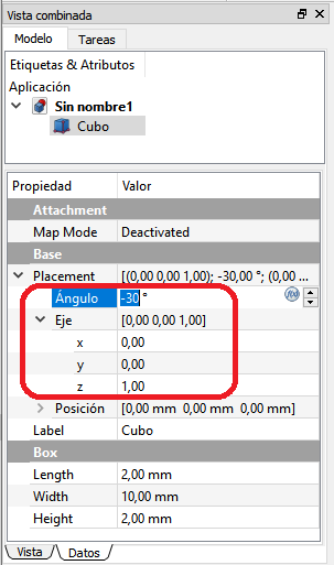
Once the bar is created, we are going to rotate it around the Z Axis.
Select the Data tab and change the Angle to a negative value of -30º
The axis of rotation chosen will be the vertical axis or Z axis. For that reason the Axis will have a value of 1 in Z and will have a value of 0 in the other axes.
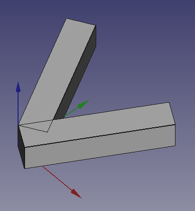
The object will rotate as it appears in the following figure.
Now we add one more cube and resize it just like we did with the previous cube.
Length (Length) = 2
Width = 10
Height (Height) = 2
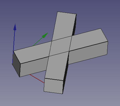
Once the size has been changed, we also rotate the new piece on the z axis with a positive Angle of 30º (in the opposite direction to the previous piece).
Finally, we can move the new part (Cube001) to the position
x = 5, y = -1, z = 0
to form an X.
Exercises
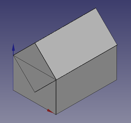
Create the figure below by rotating a cube.
Choosing in the menu
View...Drawing style...Wire modelthe figure is displayed as follows.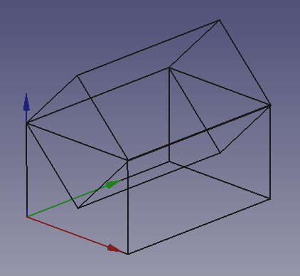
To build the base we will create a cube and change the following dimensions
Length (Length) = 14
Width = 20
Height (Height) = 10
The roof will be created from a cube by changing the following dimensions
Length (Length) = 10
Width = 20
Height (Height) = 10
The resulting piece must rotate 45º on the Y axis
Once tapped, the piece must be translated up until it is placed as a roof.
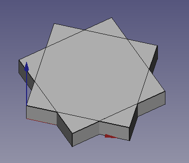
Create the following figure with two cubes.
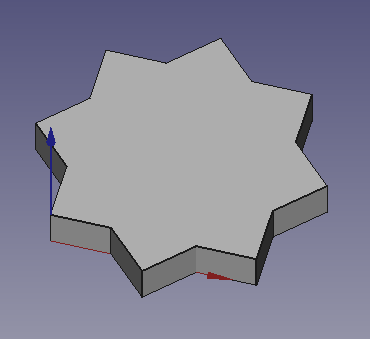
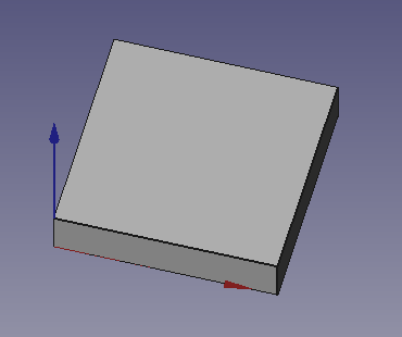
First create a new cube and change its Height to 2 millimeters.
Copy and paste the previous cube to have 2 equal cubes.
The second cube must be rotated 45º with respect to the Z axis, but we are going to rotate it around its center.
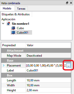
First we open the dialog box for performing complex turns. Click on Placement and then on the square on the right.
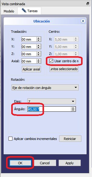
Once opened, we must check the rotation box with respect to the center of the figure, rotate an Angle of 45º and click on OK.
In the end we will obtain the following figure.
All that remains is to join the two pieces and simplify the shape (refine).
Video-tutorial
Video: Rotating I go.