13. The current source
This circuit serves to generate a current that will remain constant, regardless of the voltage at its output. It is a circuit widely used to polarize other transistor stages, such as the differential pair, to power constant current LED diodes, send information immune to electrical noise, etc.
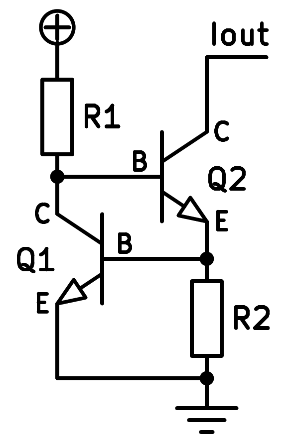
Schematic of a constant current source based on NPN transistors.
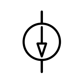
Symbol of a constant current source.
Operation and calculations
The function of each component is the following:
Resistor R1 biases the base of transistor Q2, which begins to conduct current.
As transistor Q2 conducts current, the voltage of resistor R2 begins to rise, until it reaches approximately 0.6 volts, which is the moment at which transistor Q1 begins to conduct current.
As transistor Q1 conducts current, the current in resistor R1 escapes through the collector of transistor Q1 and stops feeding the base of Q2.
The end result is that a practically constant voltage is maintained at the base of Q1 and therefore at the resistor R2. This constant voltage means that a practically constant current will flow through the emitter of Q2 and, neglecting the base current, through the collector of Q2.
Applying Ohm's law:

Being:
I_R2 = Current flowing through resistance R2 in amperes [A]
V_be = Voltage between the base and emitter of transistor Q1 in volts [V]
R_2 = Resistance R2 in ohms [Ω]
La tensión V_be puede variar, pero suele mantenerse en un valor alrededor de 0,60 Voltios.
Exercises
Draw a simplified schematic of a constant current source based on NPN transistors.
Draw the symbol for the constant current source next to it.
Draw a realistic schematic of a constant current source based on NPN transistors, which feeds a resistor.
What is the main function of a current source? What applications does it have?
In the simulation of the constant current source we can check how external changes affect it.
Change the supply voltage from 9 volts to 18 volts in steps of 3 volts at a time and record in a table how the current through the collector of the transistor varies with the change in supply voltage.
In the simulation of the constant current source we can check how external changes affect it.
With a supply voltage of 9 volts, change resistor R3 to the values 2000Ω, 1000Ω, 100Ω, 10Ω. Write down in a table how much the collector current is for each of the resistance values.
Design a constant current source that operates with a supply voltage of 12 volts and a collector current of 10 milliamps.
To achieve this, change the supply voltage to 12 volts and calculate the necessary resistance R2 with the formula:

Cambia en el simulador anterior los valores de tensión de alimentación y de resistencia R2 para comprobar que funcionan correctamente.
Design a constant negative current source in the circuit simulator. The shape of the circuit will be the same as the previous simulated source, but using PNP transistors and connecting the circuit in a horizontal mirror. That is, resistor R1 will be connected to the negative of the battery and resistor R2 will be connected to the positive of the battery.