21. The peak detector
The peak detector is a circuit that maintains at its output the voltage peak value found at the input. It is composed of a half-wave precision rectifier and an RC filter at the output, which memorizes the highest voltage level of the rectifier output.
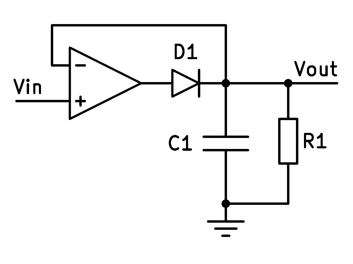
Scheme of the peak detector.
Operation
The diode at the output of the operational amplifier prevents it from delivering negative current. As the operational unit will only be able to deliver positive voltage and current, the output capacitor will rise in voltage until it equals the maximum input voltage and will maintain this voltage.
The 10k resistor will cause the capacitor to discharge little by little and its voltage will tend to be zero volts.
In this way, the maximum input voltage, or peak value, will be stored for a time in the capacitor, which will gradually lose that maximum voltage to adapt to other lower voltage peaks that arrive later.
Simulation
In the following simulation we can see a peak detector to which an alternating amplitude-modulated voltage arrives. The maximum input voltage is reflected in the output value of the circuit.
Exercises
Draw the schematic of a peak detector.
What type of feedback does the peak detector have and why?
What function does a peak detector circuit perform?
What voltage gain will a peak detector have and why?
Modify the previous peak detector simulation to make a demodulator circuit:
- Increases the frequency of the Amplitude Modulated carrier signal up to 1000 Hz.
- Decrease the value of the capacitor until the output signal is equal to the envelope of the input signal.
- Draw a graph of the input voltage and another graph of the output voltage.
What happens if we change the direction of the diode? Simulate the change to check the new operation.
What could we call this new circuit?