12. The differential pair
The differential pair is composed of two transistors with both emitters connected to a current source.
When the voltage across the bases is the same, the current through the collectors remains the same in both transistors and, therefore, does not amplify the signal.
When the voltage at the base of one transistor is greater than at the base of the other transistor the current is diverted towards the transistor with the higher voltage at the base and this 'differential' signal is amplified at the output.
Therefore this amplifier only amplifies the differences between two input voltages and does not amplify (reject) the changes that are common to the two input voltages.
This amplifier (the differential pair) is used at the input of the very popular operational amplifiers, which will be seen later.
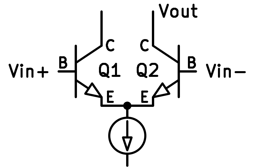
Schematic of two NPN transistors in differential assembly.
The symbol connected below the emitters of the transistors is a constant current generator.
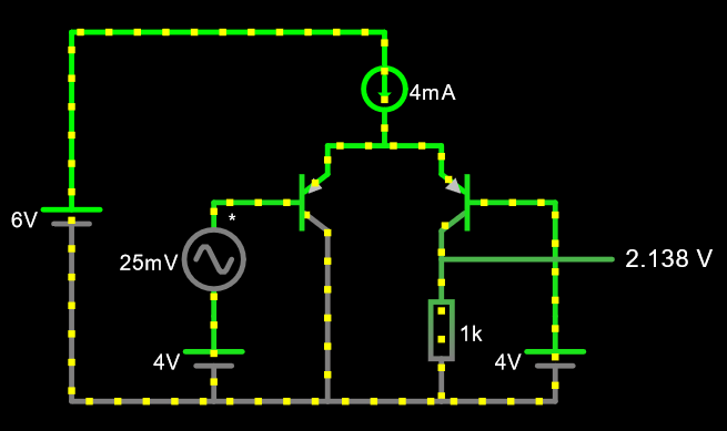
Simulation
Below you can see the simulation of a differential pair with two NPN transistors. The differential input signal has 25 millivolts of peak amplitude and the output signal has 1 volt of peak amplitude. This means that the stage has a voltage gain at the output of 40 times the input voltage.
Exercises
Draw a simplified schematic of two NPN transistors working in differential pair configuration.
Draw a realistic schematic of two NPN transistors working in differential pair configuration.
What is the main objective of a differential pair? In what popular devices is differential pair used?
Modify the two 1-volt voltage generators in the simulation so that they deliver 2 volts. How does the output change?
If we increase the voltage of two generators to 3 volts, how does the output change?
What does this operation mean?
In the circuit simulator, carry out a simulation of a differential pair with PNP transistors. The scheme will be like the following figure:
What differences in operation does the previous circuit have compared to the first simulated circuit?
What common voltage range does the above circuit accept at its input?