16. The follower amplifier
This is the simplest scheme that can be connected to an operational amplifier. This scheme serves to obtain the same voltage at the output of the amplifier as its positive input.
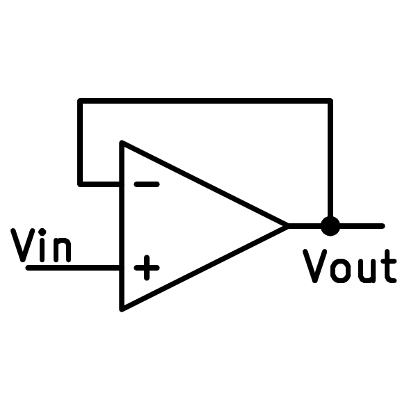
Scheme of the follower operational amplifier.
This scheme is useful when we want to obtain a stable voltage with low output resistance from a voltage source with high resistance, which would change its voltage a lot if we connect current to it.
A practical example of using a follower amplifier is the following circuit that generates a virtual ground voltage from a resistive voltage divider:
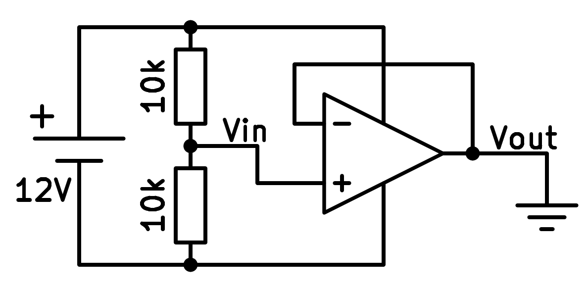
Follower amplifier used to generate a virtual ground voltage.
Negative feedback
For an operational amplifier to be stable it must have negative feedback. This means that the output voltage must reach the negative terminal of the input.
If the output voltage increases, the negative input voltage will increase and this will cause a decrease in the output voltage.
If, on the other hand, the output voltage decreases, the negative input voltage will decrease and this will produce an increase in the output voltage.
As output voltage changes tend to compensate, the result will be that the output will have the same voltage as the input.
With negative feedback the two input terminals will have the same voltage.
Simulation
In the following simulation we can see a follower amplifier used to copy the voltage of a zener diode. This allows a circuit to be fed with a relatively high current, which would change the zener voltage if we connected a load directly.
Exercises
Draw the simplified schematic of a follower operational amplifier.
Draw a real schematic of a follower operational amplifier that can be used to generate a virtual ground.
Draw a real schematic of a follower operational amplifier that serves to generate a stable output voltage from a zener diode.
In the simulation above, change the value of resistor R1 with the control bar on the right. What happens to the resistance voltage? Why do you think this happens?
In the simulation above, change the value of resistor R2 with the control bar on the right. What happens to the resistance voltage? Why do you think this happens?
In the above simulation, if we make the value of resistor R2 very low there will come a time when the op amp will not be able to deliver enough current and the voltage will drop. What maximum current can the op amp deliver?
Using Ohm's law, calculate the minimum resistance that we can connect so that the output voltage remains at 5 volts.