19. The non-inverting amplifier
In this circuit the operational amplifier amplifies the input signal and a non-inverting signal output is obtained.
The non-inverting amplifier has negative feedback because the output voltage produces a current that reaches the negative input terminal through resistor R2.
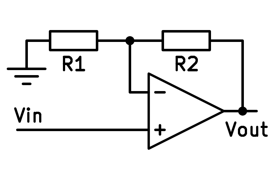
Scheme of the non-inverting operational amplifier.
Profit calculation
The gain formula for this amplifier is as follows:

At least the profit will be worth one unit. This occurs in the event that resistance R1 is very large and resistance R2 is very small. At the limit we find the unit gain of the voltage follower, which has an infinite resistance R1 and R2 equal to zero.
Input and output resistance
The input resistance will be equal to the + input resistance of the op amp, which is ideally infinite. In practice it has values greater than 100 million ohms. This large input resistance is an advantage compared to the inverter scheme, which has a relatively low input resistance that absorbs current from the input signal.
The output resistance will be very low, ideally zero, because the output is directly connected to the output of the op amp.
Simulation
In the following simulation we can see a gain 3 inverting amplifier that amplifies a sinusoidal input signal.
Exercises
Draw the simplified schematic of a non-inverting operational amplifier.
Write the formula for the gain of the non-inverting operational amplifier above.
What type of feedback does this circuit have? What happens to the input voltages with that type of feedback?
Draw two graphs representing the input voltage and output voltage of the simulated noninverting amplifier.
What peak voltages do each of the two graphs represented have? You can stop the simulation and zoom to full screen to measure more accurately.
Calculate the resistors needed to make a non-inverting operational amplifier have a voltage gain equal to 9.
Draw a realistic schematic of this amplifier, with a supply of +-15 volts and a triangular voltage input of 1 volt peak.
With the help of the circuit simulator draw the diagram of a non-inverting operational amplifier based on an ideal operational amplifier that amplifies the signal of a square wave voltage generator with a peak voltage of 1 volt. The voltage gain must be 2.
Plot the generator voltage signal and the operational amplifier output voltage signal on the same oscilloscope.