17. The inverting amplifier
In this circuit the operational amplifier inverts and amplifies the input signal.
The inverting amplifier has negative feedback because the output voltage produces a current that reaches the negative input terminal through resistor R2.
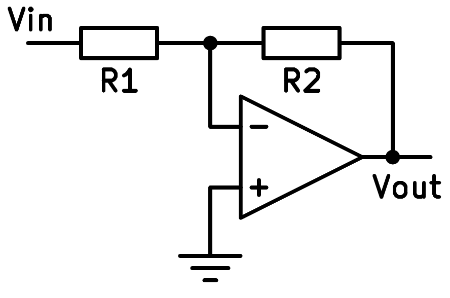
Scheme of the inverting operational amplifier.
Profit calculation
The gain formula for this amplifier is as follows:

To calculate the gain of this scheme we must take into account that with negative feedback the two inputs - and + will have the same voltage. This means that the voltage at the - input will be equal to zero, since the + input is connected to ground.
From this premise, the input current will be equal to Vin / R1. That same current will be the one that flows through R2, since no current flows through the input of the operational amplifier. In that case the voltage across R2 will be equal to the current through the resistance Vout = R2 · Vin / R1. Rearranging we get the previous profit equation.
Input and output resistance
The input resistance will be equal to resistance R1.
The output resistance will be very low, ideally zero, because the output is directly connected to the output of the op amp.
Simulation
In the following simulation we can see a gain 5 inverting amplifier that amplifies a small sinusoidal input signal.
En color verde podemos ver la forma de onda de la tensión de entrada y en color rojo podemos ver la forma de onda de la tensión de salida.
Exercises
Draw the simplified schematic of an inverting operational amplifier.
Write the formula for the gain of the inverting operational amplifier above.
What type of feedback does this circuit have? What happens to the input voltages
-and+of operational amplifier with that type of feedback?Draw two graphs representing the input voltage and output voltage of the simulated inverting amplifier.
What peak voltages do each of the two graphs represented have? You can stop the simulation and zoom to full screen to measure more accurately.
Calculate the resistors needed to make an inverting operational amplifier have an input resistance of 1000 Ohms and a voltage gain equal to -100.
Draw a realistic schematic of this amplifier, with a supply of +-6 volts and a sinusoidal voltage input of 0.1 volts.
With the help of the circuit simulator draw the schematic of an inverting operational amplifier based on a real operational amplifier (LM324) that amplifies the signal of a square wave voltage generator with a peak voltage of 1 volt. The voltage gain must be -2.
Añade la tensión de alimentación del amplificador operacional con la fuente de tensión de un terminal (letra V mayúscula).
Plot the generator voltage signal and the operational amplifier output voltage signal on the same oscilloscope. Delete the yellow current graphs.