18. The summing amplifier
In this circuit the operational amplifier inverts and amplifies the input signals, which can be two or more signals.
The inverting amplifier has negative feedback because the output voltage produces a current that reaches the negative input terminal through resistor R3.
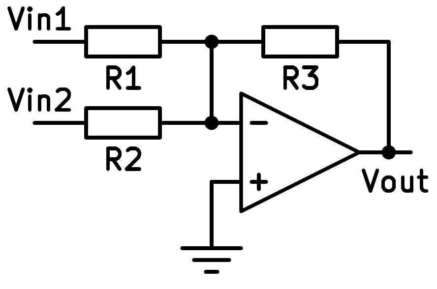
Scheme of the inverting adder operational amplifier.
This circuit is based on the inverting amplifier, with which it has great similarity.
By having the input voltage negative zero volts at all times, the input voltages do not affect each other.
Profit calculation
The formula for the output voltage of this amplifier is as follows:

The gain of each input depends on the resistance of each of the inputs and does not have to be the same in both.
The input resistance will be equal to resistance R1 for input 1 and equal to R2 for input 2.
The output resistance will be very low, ideally zero, because the output is directly connected to the output of the op amp.
Simulation
In the following simulation we can see a summing amplifier that will add two sinusoidal signals of different frequency and amplitude.
Exercises
Draw the simplified schematic of a summing operational amplifier.
Write the formula for the output voltage of the above summing op amp.
What type of feedback does this circuit have?
What happens to the input voltages with that type of feedback?
Does the input voltage V_in1 affect the input voltage V_in2?
Draw three graphs representing the input voltages and output voltages of the simulated inverting amplifier.
What peak voltages do each of the three graphs represented have? You can stop the simulation and zoom to full screen to measure more accurately.
Calculate the resistors needed to make a summing operational amplifier have a voltage gain equal to -5 on the first input and -10 on the second input.
Draw a realistic schematic of this amplifier, with a +-15 volt supply and two 1 volt sinusoidal voltage inputs.
With the help of the circuit simulator draw the diagram of a summing operational amplifier based on an ideal operational amplifier that amplifies:
- The signal from a square wave voltage generator with a peak voltage of 1 volt and a frequency of 20Hz.
- The signal from a triangle wave voltage generator with a peak voltage of 1 volt and a frequency of 40Hz.
Plot the voltage signals from the generators on the same oscilloscope and, on a different oscilloscope, plot the voltage output signal of the summing amplifier.