11. The push-pull scheme
The push-pull scheme, also called push-pull, is a circuit used in the output stages of electronic circuits to deliver both positive voltage and current as well as voltage and negative current.
The scheme uses an NPN transistor to deliver positive current and voltage and uses a PNP transistor to absorb current and deliver negative voltage.
Both transistors are in common collector or "emitter follower" which, as we remember, is a configuration that amplifies the output current, but does not amplify the voltage.
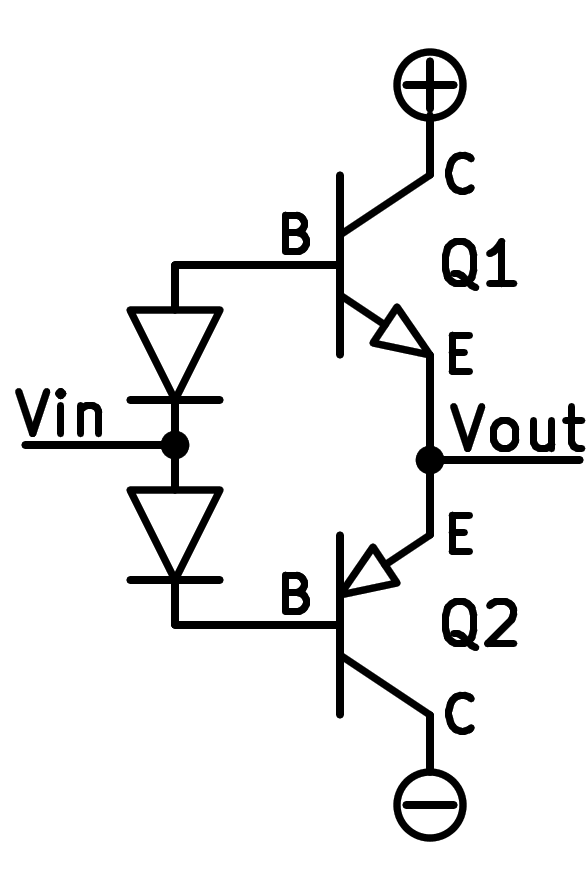
Schematic of two bipolar transistors in push-pull assembly.
The two diodes at the bases of the transistors serve to maintain a voltage of 1.2 volts between the bases, which coincides with the bias voltage of the two transistors.
Simulation
Below we can see a simulation of a push-pull circuit that manages to power a load with positive and negative currents. The upper part of the circuit is symmetrical with respect to the lower part. Each of the transistors is responsible for conducting a part of the current. The upper NPN transistor conducts the positive current and the lower PNP transistor conducts the negative current.
Exercises
Draw a simplified schematic of two bipolar transistors working in push-pull configuration.
Draw a realistic schematic of two bipolar transistors working in push-pull or push-pull configuration.
What function does a push-pull stage perform and where can they be found?
What type of amplification does a push-pull stage perform?
What voltage gain does the simulated push-pull stage have?
Remember to stop the circuit simulation so that you can easily measure the maximum and minimum input voltage and output voltage values.
The formula for voltage gain is:

What is the current gain of the simulated push-pull stage?
The formula for current gain is:

Search the Internet for the data sheet of the popular op amp LM321. Draw the output stage, based on a push-pull circuit.