4. The zener diode
Rectifier diodes support a high negative voltage without conducting. However, the zener diodes are designed so that they can conduct current when the negative voltage is less than the breakdown voltage, with a value that can be between 2 and 6 volts.
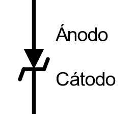
Zener diode symbol and name of its terminals.
Note
There are diodes that conduct current with reverse voltages greater than 6 volts. This type of diodes are based on the avalanche effect, a different effect from the zener. However, we can find avalanche diodes called zener diodes or vice versa, because both have the same function of conducting current at a specific reverse voltage.
Zener diodes allow the construction of limiting circuits that prevent the voltage from exceeding a value, determined by its breakdown voltage. With zener diodes, very precise voltage references can also be manufactured, used in the highest precision devices.
In the following simulation you can see the characteristic curve of a zener diode. The diode conducts current when the positive voltage exceeds 0.65 volts, like any rectifier diode. But it also conducts current when the voltage is negative and reaches a threshold called breakdown voltage, which in this case is 5.6 volts.
Voltage reference
In the circuit below you can see one of the applications of the zener diode, reducing a variable input voltage to a relatively fixed output voltage. This is a very simple, but functional scheme. In practice, more elaborate and much more precise circuits are used to construct fixed voltage sources.
Exercises
Draw the symbol of the zener diode with the name of its terminals.
What other diodes are related to zener diodes because they perform the same function? How are they different from zener?
Draw the graph of voltage (on the x-axis) and current (on the y-axis) of the zener diode from the first simulation.
Draw horizontal and vertical marks on the axes that correspond to the voltage and current values used.
Draw a circuit with a zener diode that limits the voltage to 5.6 volts from a supply voltage of 12 volts.
With the help of the circuit simulator, adjust the bias resistance of the zener diode so that it conducts approximately 20 milliamps.
How much is the bias resistance?
Make the circuit in the following image with the circuit simulator.
This circuit is a regulated linear power supply. It has a full wave rectifier with filter capacitor and a voltage regulator based on a zener diode and a transistor.
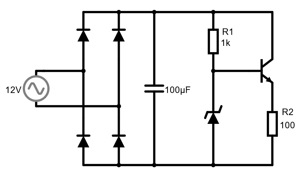
Regulated power supply with zener diode and a transistor.
Add an oscilloscope with the capacitor voltage and add the voltage on resistor R2 to that same oscilloscope.
What voltages do the two components have? Draw an approximate graph of the shapes of the two stresses on the same graph.
Investigate What function does the zener diode perform in the above circuit? What function does the transistor perform?